
Installing a DCC decoder in a N Scale "Emily" locomotive
by Doug Wood
Bachmann trains have a fairly complete line of N scale Thomas the Tank Engine engines/characters, but none of these come with Digital Command Control (DCC) decoders. Here I describe installing a decoder in the "Emily" engine from the collection, Bachmann part #58795, a Stirling Single characterized by its large, single drive wheel.


This was a challenging installation as there is very little space in the model for the decoder. Thomas and Percy, which I have also converted to DCC, were a bit easier because they have somewhat larger cabs than Emily. I first tried a Digitrax DNZ126T but I just couldn't manage to fit it in the cab (a bit too wide). I then tried a Train Control Systems (TCS) Z2 | TrainControlSystems decoder which worked much better.
I always start decoder installations by testing the model first on a DC track to make sure it will actually run.
We begin by removing the shell by unscrewing the four screws between the wheels on either side of the big drive wheel:
Of course, you will want to carefully save these screws to reassemble the model later (they are all the same size). Lift the shell up by the cab end first, then pull it off (be careful with the fine gold line art on the model as it can rub off).
With the shell removed you should find this:
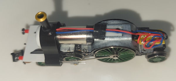
Trim the wires on the loco to something like this:

Strip about 1/4" of insulation from all the loco wires.
On the TCS Z2 decoder, cut the red and black (track power), and gray and orange (motor) wires to about 1" and strip 1/4" of insulation their ends as well. All the other wires on the decoder can be cut off as we will not be using them in this model. (I first tried to leave about 1/2" of these wires in case I wanted to use them in another model later, but there just was not enough room in Emily for them so I cut them nearly completely off in the end).
We will solder the decoder wires to the model like this:
Z2 Decoder Emily
red red (track+)
black black (track-)
orange blue (motor+)
gray orange red (motor-)
Note: The motor wire colors are different than what you will see in the pictures below. More on this later.
When soldering, you will find it very helpful to have a "helping hands" like this
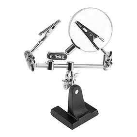
to hold the two ends of the wires together ready to solder the splice (sorry I did not include the other alligator clip of the helping hands in this photo but it is holding the black wire of the decoder in place).

Solder all of the wires like this (note the motor wires really should be reversed from what is pictured here.

Solder all of the wires like the photo above (note the motor wires really should be reversed from what you see in this picture -- more on this later).
I am not using shrink tubing here as I thought it might add too much stiff material that would be hard to fit into the model during reassembly. Instead, I cut small rectangles of Kapton tape using the ESD safe plastic bag that the decoder came in. One piece has been removed in this photo):

I used tweezers to place the Kapton on each splice like this:

Then folded the long sides of the rectangle over to insulate each splice:

Do this for all the splices and then carefully fold the splices and the decoder into something that looks like this:

Note: I found that I had to cut off all the unused wires on the decoder shorter than this to fit it all back into Emily.
At this point it is a good idea to try putting the model, with no shell, on your DCC programming track and see if it will program. If it is not programming, you may need to give Emily a nudge as I think the big wheel mechanism is a bit sticky. If you still can't program, check all of the soldering to see if some splice is wrong or came loose.
Now you are ready to fit the shell back on to the chassis. I don't have photos or a video of this, but I first started by trying to push the Z2 up in the Emily's cab on an angle like you see in the photo above, then tried to get the boiler end of the shell to hook under the smokestack. Next, I started to bring the cab end of the shell down on to the chassis. I used a small screwdriver to carefully stuff the wires up into the shell as I brought the cab end of the shell down. Turn the model over and look to see that you do not have any wires visible in the screw holes (this happened to me, and I had to use the small screwdriver to push them up into the shell.
When you have the shell all the way down, find the 4 screws removed at the start and reinstall them.
Put the loco on your DCC programming track and see if you can program it after installing the shell. Because it has no headlight, you can't see if the decoder has power (this is usually the first thing I check). If it will not program, try removing the shell and try programming it without the shell.
Hopefully you will get it running like this on your DCC layout:

Note: when I first completed this installation, my Emily ran the wrong direction; when the DCC throttle was set to forward it ran backward. That is why I have said to reverse the motor wires from what you see in the photos above. If you have a decoder installation that comes out running the wrong way you can, of course, resolder the motor wires with the opposite polarity, but it is far easier if you have it all reassembled to leave the wires alone and just use your DCC system to change the value of CV 29 which sets the direction that the loco will run (i.e. the motor polarity). Read CV29 first, and if it is even, add 1 to its current value and set CV29 to the new, odd value. If the value is odd, then subtract one to make it even and use that to set CV29. In the wiring mapping I give above, I have swapped the motor wires colors so this should not happen to you, but if you get it backwards in the end, just change CV29.
Good luck and Happy Modeling!
(617) 327-4341